
4. Ethernet networks standards.
1. . Ethernet, IEEE 803.3 10 base 5 and Ethernet, IEEE 802.3 10 base 2 - 2. Ethernet, IEEE 802.3 10 Base T RJ45 - 3. Ethernet 100 bases T RJ45, fast Ethernet - 4. Giga Ethernet - 5. Network card - 6. Duplex Half and Duplex Full - 7. Connection RJ45 - 8. Networks RJ45, problems of connection, tests equipments - 9. Mac address
 The connection between computers requires a network card in each PC (also called NIC, Network Interface Card). Local network cards commonly are Ethernet. This chapter includes all Ethernet connections and wiring (manufacturing, precaution,...). The following includes the Ethernet hubs (hub, switch, router,...).
Ethernet LAN dates from the end of the 1970s, it follows from DEC, Intel and Xerox, studies prior to standardization. This explains that the upper layers of the OSI model are not specified. All PCs can communicate on the cable computer network simultaneously. To avoid that two stations communicate at the same time, have used the contention. The main method in a local area network (LAN) is CSMA/CD (Carrier Sense Multiple Access), with a detection of collisions. It is used by Ethernet networks. When a station is transmitting, listen if other equipment is not also engaged in issue. In the event of two simultaneous shows (a collision), the station stops to issue, prior to reissue his message after a fixed delay. This technique is random, we cannot predict the time used to transmit a message in transmission and reception.
1. Ethernet, IEEE 803.3 10 Base 5 - IEEE 802.3 10 Base 2
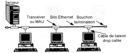 10 Base 5 is the original version of Ethernet. It allows a speed of 10 Mb/s on a coaxial cable of 500 meters by segments (so a bus topology).
Network Interface Card ensures the physical adaptation and manages algorithm CSMA/CD. As in all coaxial connections, the 2 ends of the cable are connected to a stopper (it is also called resistance of termination), a specific resistance which attenuates the reverberation of the signal on the cable.
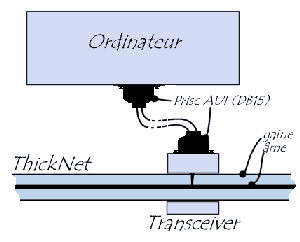 The drop cable consists of twisted pairs and can
have a maximum length of 50 meters. The coaxial cable is a thick cable of yellow
color an half-inch in diameter of the type BELDEN 9580.
The overall length of the network can reach 2,5 kilometers with 100 points of
connection.
The drop cable consists of twisted pairs and can
have a maximum length of 50 meters. The coaxial cable is a thick cable of yellow
color an half-inch in diameter of the type BELDEN 9580.
The overall length of the network can reach 2,5 kilometers with 100 points of
connection.
The 10 base 5 is used practically more only in the disturbed environments (electromagnetic radiation) or when one wants to guarantee the confidentiality of the exchanges (non radiation for coaxial cable).
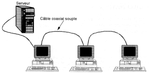 A version of IEEE 802.3 10 base 2 is better known. It uses a thin coaxial cable (Thin Ethernet) with a maximum length of 185 meters to 30 stations maximum. Each station is connected to the coaxial via a BNC-type T, 50 cm minimum must separate two stations. Again, using a resistance of 50 ohm termination
(Cap).
A version of IEEE 802.3 10 base 2 is better known. It uses a thin coaxial cable (Thin Ethernet) with a maximum length of 185 meters to 30 stations maximum. Each station is connected to the coaxial via a BNC-type T, 50 cm minimum must separate two stations. Again, using a resistance of 50 ohm termination
(Cap).
This connection is suitable for 2 or 3 PC, little more.
2. Network Ethernet, IEEE 802.3 10 Base T
A first version (802.3 1 base 5 or Starlan) uses the Pre-wired for the phone wiring in buildings. It is based on a star topology via hubs with a maximum distance of 250 meters.
 The next version (Ethernet 802.3 10 base T) is based on this standard but with a higher speed (10 Mbps) over a maximum distance of 100
meters. 10 Base T uses two telephone pairs (4 wires) with a maximum speed of 10 Mb/s with again a star topology. Nodes consist of hubs (hub, switch,
router).
The next version (Ethernet 802.3 10 base T) is based on this standard but with a higher speed (10 Mbps) over a maximum distance of 100
meters. 10 Base T uses two telephone pairs (4 wires) with a maximum speed of 10 Mb/s with again a star topology. Nodes consist of hubs (hub, switch,
router).
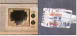
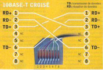
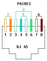
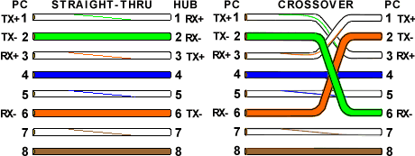
The wiring under a RJ45 10Base-t uses 4 wires (for 8 accessible in the connector). The wires can be purchased commercially, but can easily be manufactured. Generally, the 8 wires are connected by RJ45 but the 10 base T and 100 base T use only 4 (Giga Ethernet, yes). Two connections are proposed, straight or crossed. Without hub (Connecting 2 computers) or between two hubs, the son must be a cable Crusaders as below. The polarities and the pairs must be matched.
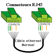
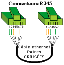
Cable straight RJ45 10 Base T and 100 base T, between a hub and a station) and a Crossed Rj45 cable between two PCs or two hubs (switch, Hub, router,...)
Why respect wiring per pairs.
 An electric current automatically induces a magnetic field in the vicinity which in turn causes a flow of current. This causes parasites on the network
cabling.
An electric current automatically induces a magnetic field in the vicinity which in turn causes a flow of current. This causes parasites on the network
cabling.
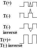
Initially, the network adapter is signal on the form T + and T-(inverse signal). If a parasite is induced on the wire during transmission. As the pairs are twisted, electrical disturbances caused by induced currents will be generally the same on the same pair but different from one pair to another.
Invert T (-). The useful signal and the parasite are reversed. Summing T (+) and (-) T inverted, the signal is double but the parasite is removed (or the less markedly reduced).
Material necessary for a cable RJ45:
- Cable 4 twisted pairs category 5
- Connectors RJ45 to crimp category 5
- Sleeves rubber, to avoid dividing the cable.
- A grip to be crimped and if the grip does not include it: cutting pliers and a grip to be stripped.
Procedure to be followed:
- To thread the sleeve on the cable.
- To strip the external sheath on approximately 15 mm.
- For the cord crossed, Trier wire according to the diagram below.
- To maintain wire in place by respecting the pairs and to cut them well on line. There must remain approximately 13mm, the end should not form an arc of circle.
- To place wire in the connector while supporting on the whole of the wire so that the pairs return until the bottom of the connector.
- To crimp the connector with grip.
- To plug in the sleeve.
Check, by transparency, the good state of your assembly, if the wire arrive well in end of connector.
3. 100 Bases TX and 100 Base T4, Fast Ethernet
Since 1992, one uses the 100 base T. The theoretical flow is 100 Mbps. The fast Ethernet also obliges to use concentrators of the hub type or switch.
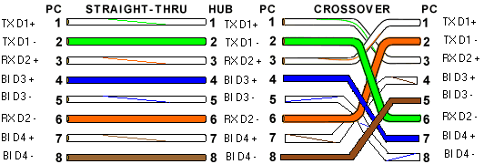
One finds 2 category of 100 Base T: 100 Base T4 (obsolete) and 100 Base TX. The 100 Base TX uses same the 2 pairs that the 10 Base T On the other hand, the 100 T4 Base uses the 4 pairs. Nevertheless, the 100 T4 base (almost more used) simultaneously uses 3 pairs for the emission and the reception. This mode cannot thus use Full Duplex (simultaneous bidirectional communication). It can be used on cable of category 3, 4 or 5.
In 100 base TX, wiring is the same one as in Ethernet bases 10, only the cable must be of better quality (category 5) and the 4 others wire must be connected according to the colors below. Attention which each "technician" often uses his own code of colors. The cross cables use the two same crossings that into 10 base T.
Normal and cross cable RJ45 100 Base TX diagram
Normal and cross cable RJ45 100 T4 Base diagram
4. Ethernet gigabit.
If at the beginning, the gigabit used an optical fiber connection, it is replaced by a connection of the type RJ45 of class 5e (with a limitation of distance limited to 100 meters). The gigabit uses the same format of screens of data that the 10 Base - T and the 100 Base TX and the same anti-collision protocol, namely the CSMA-CD (Carrier Sense Multiple Access with Collision Avoidance). This standard makes it possible each computer to announce that it will transmit a message before transmitting the data on the network (what avoids the collisions).
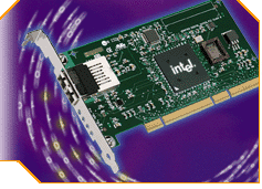
Network adapter INTEL PCI-X 64 bits - 133 MHz
(1 Gbit/s on multimode optical fibre (MMF): 500 m)
1000 Base LX
(1 Gbit/s on monomode optical fibre (SMF): 3000 m)
1000 Base C
(1 Gbit/s out of 4 pairs UTP5: 25 m)
1000 Base T - 1000 Base TX IEEE 802.3 ab ratified on June 26, 1999
1 Gbit/s on cable category 5, transmission out of 4 pairs (250 Mbits/paire) over a 100 meters length)
|
Norme |
Speed |
Out distance |
Media |
10 BaseT |
10 Mbps |
100m |
Copper |
100 BASE-TX |
100Mbps |
100m |
Copper |
100 Mbps |
412 m 2 km |
half Duplex Multimode Optical fiber Multimode Full Duplex Optical fiber |
|
1000 BASE-LX |
1000 Mbps |
5Km |
Individual-mode Optical fiber |
1000 BASE-SX |
1000 Mbps |
550m |
Multimode Optical fiber (50u) |
1000
BASE-CX |
1000 Mbps |
25m |
Copper |
1000 BASE-T |
1000 Mbps |
100m |
Copper |
1000 Mbps |
70 km |
Optical fibre |
Wiring on twisted pairs of 1000 C and 1000 TX is identical to that of the 100 T4 Base, including for the Ethernet cables cross RJ45.
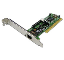
5. Ethernet Network adapter
PC use three types following speeds: 10, 100, and Giga Ethernet. All cards integrate an RJ45 connector except first base 3Com T who agreed that the coaxial + connector owner. 10 MB cards increasingly incorporate a coaxial connector. Hubs 100 base TX enable links 100 Mb and 10 Mb, the Giga rarely accept the 10.
Network cards are connected in an internal bus: ISA, PCI, PCI-Express or PCI-X for servers. There is a sometimes incompatibilities between 3.3V PCI cards and motherboard 5V (older Pentium). Some boards feature a socket for an EPROM. This allows to boot the PC via the network (without hard drive).
Each network Ethernet RJ45 adapter includes 2 LED. The first, usually green, indicates that the adapter is connected to a hub via a cable. The second, orange or green, indicates the transmission / receipt of data. The current network adapters automatically switch on each Ethernet (10 or 100) speed.
Very few exceptions (hub and switch from bottom of range), with a map in connected by RJ45 to a hub, the LED should light on the NIC and the HUB, Switch, router. In hardware, this means that it is the network access which is badly set. low.
6. Duplex Half and Duplex Full.
 A Ethernet
network adapter can be of type Half Duplex and Full duplex. The boards Half Duplex
(normal)
cannot emit and receive at the same time. By counter the boards Full Duplex (and
the switch associated) can emit and receive at the same time on channels (cables)
different. This solution makes it possible to double the rate of transfer on the
Ethernet network. For example, a board 100 bases TX (100 T4 base does not
authorize duplex Full) goes authorized a rate of transfer of 200 Mbps for 100 in
the duplex case half.
A Ethernet
network adapter can be of type Half Duplex and Full duplex. The boards Half Duplex
(normal)
cannot emit and receive at the same time. By counter the boards Full Duplex (and
the switch associated) can emit and receive at the same time on channels (cables)
different. This solution makes it possible to double the rate of transfer on the
Ethernet network. For example, a board 100 bases TX (100 T4 base does not
authorize duplex Full) goes authorized a rate of transfer of 200 Mbps for 100 in
the duplex case half.
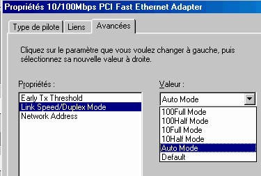
It is necessary to slow down the network (to pass into 100 Half mode or even in the event of disturbances network to oblige the board 100 Base TX to work into 10 base T). The parameter setting is done in the parameters networks by using the properties of the network adapter. Here for example the case of a Ethernet adapter at base of the circuit Realtec RTL8139D (10base T and 100 automatic base TX).
7. Wiring RJ45 Ethernet, rules, problems of connections and tests equipments
Cables RJ45 can be bought done everything. Nevertheless, in professional wiring, they are integrated in chutes, pass through walls... The solution consists in buying a grip, the connectors (with protections), the cable and to respect strictly the colors of wiring RJ45 above.
To connect two structures between them by cables brings always various types of problems.
The first remains the maximum conditions of operating. It is trying to put a wire longer than that envisaged by the standard between Hub (or a switch) and computer (100 meters for one T bases 10 or 100). First error.
If the cable is bought done everything, connection is generally good. This is valid for the small internal networks but is seldom the case for the industrial networks. As a tester of wiring network is worth easily the price of a small sporting car, better is worth to cable correctly in advance.
Each connection is limited by the number of HUBS in cascade. For a connection 10 bases T, the maximum number between 2 stations east of 4. On the other hand, it is 2 into 100 base T
In the last, cable RJ45 must be correctly posed. Among the encountered problems, one finds:
- cable network cut or scratched or folded.
- more underhand: the cable passes to with dimensions from electric cables which disturb the signal, beside fluorescent tubes or neon (minimum 50 cm). Proximity of electric motors of strong powers. The table below shows the distances minimum between the cables networks and the electric cables according to the distance.
Spacing enters the cables current strong (electrical supply network, neon) and low current (Ethernet network)
| Spacing in cm | |||||||||
| 30 cm | |||||||||
| 20 cm | |||||||||
| 10 cm | |||||||||
| 5 cm | |||||||||
| 10 m | 20 m | 30 m | 80 m | ||||||
|
Parallel advance in meters |
|||||||||
For a cable RJ45 low length, one could put the electric cables and networks in the same chutes. This would be to forget the electric safety requirements which prohibit to insert electric cables and telephone (low voltage) in the same chutes, even if it is common in the suspended ceilings in industries.
One finds on the market various types of tests equipments of the cables networks.
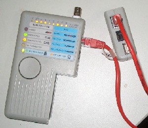 The
first (see photo) function as an ohmmeter on 8 threads. A party goes from one side of the son, the tester on the other. These devices usually detect the right cables and cables cross as well as other connectors (RJ11, RJ45, USB,...). They check only if the connection is good, not if the connection is correct. If the unit detects a wiring error, the son is bad. On the other hand, a correct display does not necessarily mean that the cable is good. A poor contact will be often considered good by the tester, but not network
connection.
The
first (see photo) function as an ohmmeter on 8 threads. A party goes from one side of the son, the tester on the other. These devices usually detect the right cables and cables cross as well as other connectors (RJ11, RJ45, USB,...). They check only if the connection is good, not if the connection is correct. If the unit detects a wiring error, the son is bad. On the other hand, a correct display does not necessarily mean that the cable is good. A poor contact will be often considered good by the tester, but not network
connection.
The part left resumes the test module, the right side, the detachable endpoint. 8 LEDs indicate whether the wires are individually correct. The left includes indications: Short (bad connection on at least one son, lack of connection to at least one son,...), CONNECTED to a cable law and no.-Parallel for a crossover cable. NO CONNECTION cable is not inserted. The price ranges from € 100 to €150.
The second type works like a network card. These devices are testing the line (and not only the son). The unit connects at the end of a cable and test the link on a HUB or switch. In this sense, they are more effective. They are a little more expensive.
The third type of tester network allows more than those of the first type:
- actual tests false contacts or cuts on each cable.
- cable length failure on a wire (or several), the distance to the when it is cut.
- various electromagnetic disturbances which pass the distance.
The price is close to 10.000 EURO.
8. MAC address
 Each network adapter is characterized by a MAC
address. This address is single for all the boards networks in the world. It
consists of 6 bytes of the type XX.XX.XX.XX.XX.XX or each XX vary from 0 to 255.
The address is often given in form hexadecimal. For example 4D.FF.56.D2.AF.26.
Each network adapter is characterized by a MAC
address. This address is single for all the boards networks in the world. It
consists of 6 bytes of the type XX.XX.XX.XX.XX.XX or each XX vary from 0 to 255.
The address is often given in form hexadecimal. For example 4D.FF.56.D2.AF.26.
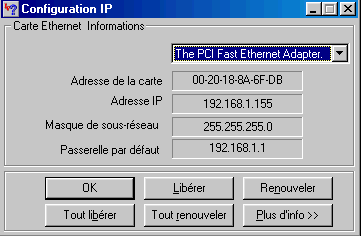
In Starts - > Execute, type command WINIPCFG (present in the Windows repertory under Windows 98) or ipconfig/all in a window DOS (Windows 2000, XP and later) for given the following your board network.
The address Mac FF.FF.FF.FF.FF.FF is particular, the data are sent to the whole of the network. It is the address of Broadcast.
The Ethernet protocol uses this MAC address to make communicate equipment between them via network. When a machine wants to speak with another, it sends a package on the network, containing the address MAC destination, the address MAC source, the length of the packet, the data and the CRC (Cyclic Redundancy Checking), an error control, ...
The MAC address has priority on address IP. When a communication network was established under Ethernet, DOS command arp -a makes it possible to find the MAC address of the other PC of the network.
|
Next of hardware course > Chapter 5: Ethernet concentrators: Hub, switch, router... |
| < 2. Bases of network transmissions |
![]()
The Hardware 1 course: computers and peripherals, Complete technical training
© YBET data processing 2006 -2015