
2. Introduction to electronic, electricity and binary logic.
2.1 Bases of electricity - 2.2. D.C. current - 2.3. Diode - 2.4. Alternative rectification - 2.5. LED - 2.6. Transistor - 2.7 Transformer - 2.8. Terminology and measuring units 2.9. TTL gates 2.10. Tri-state - 2.11. Binary calculation - 2.12 Tools - 2.13. Some rules for electric network.
Before returning in the meanders of the processing boards, this chapter is useful of recall (or discovered) in electronics and electricity. Computer hardware is a branch of electronics (the digital part) and electronics, a particular electricity application.
1 Base electricity.
The electrical signal can be continuous or alternate according to the shape of the signal compared to a reference voltage which one calls the ground.
In Europe, the electrical supply network is 230V alternate single-phase current (2 wires) with tolerances (110 Volts in USA). On the electrical supply transport (before arriving in your house), it is generally in three-phase current 240 V or 380 V and in high voltage to connect the various cities and villages. The alternating voltage is the average voltage of the network uninterrupted. One can consider that for a "perfect" rectification , without losses of power in the assembly of rectification; would give for 230 V alternate, of 230 V continuous.
The electronic assemblies are powered in various continuous voltages. The conversion of an alternating voltage on continues voltages use an electronic assembly indicated by the term "power supply". We will seen them in second year with the UPS and switching power supply, the first part of hardware course is interested only in the continuous voltages of weak voltages (lower than 24 Volts) and low power.
2. D.C. current
2.1. Introduction
The electric voltage continue is a linear voltage according to a reference voltage standard which one calls the ground. The D.C. (direct current) voltage can be positive or negative. For a positive voltage, the power is on from more towards the ground (0 Volt). For a negative voltage, the power is on from the ground towards the negative terminal. This is a convention since the scientists determined that electrons (and thus the current) made in fact the opposite way. An electric assembly (and thus electronics) require 2 points of connection.
Electronics in D.C. current is characterized by passive and active assemblies.
A passive assembly consist of resistances, coils and condensers and influences only the shape of the signal.
An active assembly consists of transistors. These transistors are currently assembled to form integrated circuits. A voltage on a point of an assembly (for example on the basis of transistor) will interact on the whole of the voltages of the assembly
2.2. Passive assembly and formulas in D.C. current.
 This
circuit consists of a source of continuous power supply and a resistor. The power
supply is characterized by its
voltage, its internal resistance and the
maximum current that it is likely to provide (a displacement of electrons
between the pole - battery and its pole +, even if the current moves + towards
-). Resistance, represented by teeth, is characterized by its value in ohm and
the maximum capacity which it is suitable for absorb (and to dissipate in the
form of heat). An electric source always has two terminals.
This
circuit consists of a source of continuous power supply and a resistor. The power
supply is characterized by its
voltage, its internal resistance and the
maximum current that it is likely to provide (a displacement of electrons
between the pole - battery and its pole +, even if the current moves + towards
-). Resistance, represented by teeth, is characterized by its value in ohm and
the maximum capacity which it is suitable for absorb (and to dissipate in the
form of heat). An electric source always has two terminals.
|
The basic formula of electricity, ohm's law is: I=V/R I represents the intensity of the current expressed in amps V the voltage expressed in volt R the resistance expressed in ohm. |
By this formula, more the voltage is high, more the current is important. On the other hand, an increase in the value of resistance will decrease the linear current.
The power represents energy used (case of an engine for example) or dissipated (case of an electric heating with resistance or the assembly above). Power, expressed in Watt, is given by the following formula: P=V2/R or P=I2 * R or P=I * V. It's Joule's Law of electricity
As example, with a 12 Volt battery and a 100 ohm resistance, the DC current which passes cross the resistance is I=12/100 = 0,12 amp. The minimum power which resistance owes supported without burning is thus of P=1,44 Watt. This is practically identical in AC current (electrical supply network). A fuse of 16 A in 220 V thus allows a peak load: 16*230 = 3680 Watts. This is theoretical since the power into alternate depends on the type of load (resistive, self-inductive and capacitive): according to the type of load, the signal of the current and the signal of the voltage are slightly shifted, one speaks about dephasing. As we will see it in second year, inverters (UPS) are indicated by VA (Volt Amp). The practical method to pass from the one to the other is Watt X 1,6 = VA. This formula is given as an indication for a data-processing application
A power PC of 220 Watt (alternate) thus requires an electrical supply fuse network of 1 Amp or more. This power manufactures D.C. current used by the electronic components of 23 A in 5V, 9 A in 12V, 0,5 A in -5V and - 0,5A in -12V for a standard power. The remainder is dissipated in the transformer and the circuits of rectification in the form of heat.
For fuses, do not put too just since the majority of the electronic assemblies (and power) consume definitely more with starting. As the majority of the assemblies use condensers, they must take care before normal operation of the installation. Moreover, one finds fast fuses (which cross to the least going beyond of current) and of the slow fuses (which accept a going beyond of current during a weak lapse of time). This is valid so much in the electronic assemblies than for the electric control panels networks. In the case of the electronic assemblies, to always replace a fuse by that recommended by the manufacturer: while running maximum and in type. A last thing, a fuse does not only start all. Before replacing a fuse, checking the damage further. The technique of the handyman who consists in replacing a fuse directly "to see" is dangerous, it can for example cause fires in the assemblies.
The current (with a resistive load in series!) measures itself with out of ampermeter. The voltage (continuous or alternate) is measured with a voltmeter. These two functions, with others according to the apparatuses, are gathered in a measuring apparatus which one calls multimeter.
2.3. Coils
 The self-inductive
loads are not very widespread in data-processing electronics,
except on power supply. Approximately, for a continuous
circuit, the passage of the current through a coil (serial connection)
is transparent. On the other hand, coil will smooth the variations
of voltages. A coil consists of only one winding on a ferrite core
The self-inductive
loads are not very widespread in data-processing electronics,
except on power supply. Approximately, for a continuous
circuit, the passage of the current through a coil (serial connection)
is transparent. On the other hand, coil will smooth the variations
of voltages. A coil consists of only one winding on a ferrite core
In the case of a use in an alternate assembly, the coils will smooth the parasites of the network.
2.4. The capacitor
The capacitor is largely used. Several capacitors are put in parallels on the power of the assembly and are used as reserve of energy, smoothing (controlling) the voltages between the two terminals, providing energy at the time of falls of voltage and absorbent of energy when the supply voltage is higher than that between the two terminals of the capacitor. A perhaps polarized capacitor (case of the electrolytic capacitors) or not according to the technology. In case of polarized capacitors, it is imperative to respect the terminal + and limits it - according to that of the power.
Assembly of test of a capacitor
Terminal voltage of the capacitor according to time.
The capacitor takes care through resistance for finally stopping the passage of the current and keeping the same voltage as that of the power. The passage of current is intense at the beginning, to slow down according to the load of the capacitor.
In this electronic assembly, resistance is often removed to increase the reaction speed of the capacitor. The power starts by feeding at the same time the electronic circuit and the capacitor until the terminal voltage of the electronic circuit and the capacitor are equal. As long as the consumption of the circuit is stable, the capacitor does not react. If the electronic circuit consumes more suddenly (cause a drop in the voltage with its terminals), the capacitor returns energy, thus ensuring a stability of voltage.
Notice that the line connecting it + power to + circuit is a wire of copper or other. This wire is also a resistive load of low resistance but also absorbing energy if the current consumption is important. This explains why, more the assembly consumes of current, more the wire of power must be large. The resistance of an electric wire is inversely proportional to its diameter.
3. Diodes
 The basic component of digital electronics is the diode. It consists of two
zones of silicon or polarized germanium: the anode and cathode. The working
procedure of a diode exceeds the framework of this course. In the direction
being on, the power circulates. On the other hand, in the opposite direction,
the current is blocked. The assembly below makes it possible to measure the
characteristics of a diode in direct direction (passer by). For the opposite
mode, it is enough to turn over the diode. The characteristics voltage running
of a normal diode is represented below.
The basic component of digital electronics is the diode. It consists of two
zones of silicon or polarized germanium: the anode and cathode. The working
procedure of a diode exceeds the framework of this course. In the direction
being on, the power circulates. On the other hand, in the opposite direction,
the current is blocked. The assembly below makes it possible to measure the
characteristics of a diode in direct direction (passer by). For the opposite
mode, it is enough to turn over the diode. The characteristics voltage running
of a normal diode is represented below.
Resistance used is variable, making it possible to amplify the current at the boundaries of the diode.
 In the direct direction, the current increases in an
exponential way according to the voltage (measured by the voltmeter in
parallel with the diode). From the voltage of threshold, the Iak current
increases in a linear way according to the voltage Vak (terminals of the
diode).
In the direct direction, the current increases in an
exponential way according to the voltage (measured by the voltmeter in
parallel with the diode). From the voltage of threshold, the Iak current
increases in a linear way according to the voltage Vak (terminals of the
diode).
In the opposite direction, the diode blocks the passage of the current until the maximum opposite voltage. Then, the diode lets pass all the current. The going beyond of this maximum voltage is not with the destructive departure, but the diode passes in short-circuit and the current causes a thermal dissipation in the diode which finally burn.
All the characteristics above vary according to the type of diode, diode power, the ambient temperature and the type of diode (for example Zener Diode).
4. Application, circuit of alternative rectification, graetz bridge
This assembly is a typical use of the diodes: a rectifying bridge. It will make pass an alternating voltage (that of the electrical supply network) in continuous voltage (power of the electronic circuits).
When the alternating voltage is positive, the voltage with terminal 1 is higher than that with terminal 2. The power resulting from this difference in voltage is thus on from terminal 1 towards terminal 2. It passes through the D1 diode (it is blocked with the terminal d3). Crossing the assembly uninterrupted, it returns by the diode d2. When the voltage with terminal 2 is higher than terminal 1 (negative voltage), the current passes through D4 then returns by the D3 diode.
Output voltage of the assembly is not continuous, it is only rectified. The following parts includes capacitors, coils, electronic circuits of smoothing... The PC supplies, power are not of this type, but of type "power with cutting", which dissipates less energy in the rectification part. Operation will be seen in second with the operation of the UPS and the electric apparatuses of protections.
5. LED
The LED is a special diode which emits light when a current the cross-piece in the direction passing according to a color depending on technology employed (red, green, yellow...). Like a simple diode, it blocks in the opposite direction. Their capacity of blocking in opposite voltage and the weak current which it accept does not make it possible to use them like truths diodes rectifier. The LED are used on the faces fronts of the PC to indicate the lighting of a PC (generally green) and the accesses hard disks (generally red or orange). If a LED does not ignite in the presence of the current, it is either defective (rare case in the processing repair), or the direction is reversed.
6. The transistor
A transistor consists of 3 germanium (or) silicon wafers, each polarized time. One finds transistors PNP and NPN in the case of transistors bipolar. Currently, the transistors are often of type "Mos". In spite of lower commutation rates (slower), they consume definitely less.
 The base is used as control. In the case of a transistor NPN, the voltage is
applied to the collector. If one injects by the base a weak voltage (and thus a
current), the zone P is charged, allowing the current passes from the collector
towards the transmitter. In the case of the PnP transistors, the voltages are
reversed. If one allows the passage of current of the transistor towards the
base (ground connection for example), the current is authorized transmitter
towards the collector. According to the voltage applied to the base, the passage
of collector current - transmitter will be more or less important.
The base is used as control. In the case of a transistor NPN, the voltage is
applied to the collector. If one injects by the base a weak voltage (and thus a
current), the zone P is charged, allowing the current passes from the collector
towards the transmitter. In the case of the PnP transistors, the voltages are
reversed. If one allows the passage of current of the transistor towards the
base (ground connection for example), the current is authorized transmitter
towards the collector. According to the voltage applied to the base, the passage
of collector current - transmitter will be more or less important.
 In the diagrams according to, a transistor NPN is used out of switch, it only is
practically used in data-processing electronics. A voltage of 0,5V applied on
the basis will allow the passage of the current of the collector towards the
transmitter (towards the ground), transforming the output voltage to a zero value.
This diagrams is the entry or the exit of a logical electronic circuit of type TTL
74LS (according to the place where the assembly is inserted).
In the diagrams according to, a transistor NPN is used out of switch, it only is
practically used in data-processing electronics. A voltage of 0,5V applied on
the basis will allow the passage of the current of the collector towards the
transmitter (towards the ground), transforming the output voltage to a zero value.
This diagrams is the entry or the exit of a logical electronic circuit of type TTL
74LS (according to the place where the assembly is inserted).
The collector is connected to the 5V power by the intermediary of a resistance. If one applies any voltage on the basis, the transistor blocks the current, and the exit passes to the voltage of 5 V On the other hand, if we apply on the basis a voltage of 5V in entry via Rb (1000 ohm), the current passes through the transistor, putting the exit at the ground (voltage 0), except a light residual stress of approximately 0,5 V (specific to the model of transistor). This assembly is thus reverser.
In the event of breakdown of a transistor, please use the adequate transistor. Indeed, each transistor is characterized by maximum voltages, gain,... it exists tables of equivalences.
7. Transformer
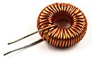
A transformer consists of wire rolled up in 2 windings or more (case of several alternative output voltages) on a ferrite core. The alternating output current (secondary) is divided by a report/ratio with the current of entry (and thus of the voltage) by a coefficient depend on the report/ratio of the number of windings of entry/a number of windings of exits. A transformer functions only with AC current. A D.C. current in the primary education does not have any effect on the exit of the transformer.
It is used in the case of a circuit of rectification by diodes like above dividing the voltage of entry of the network (230 V alternate) and allowing an adequate voltage the exit (less than 30 volts in all the cases). For recall, at the boundaries of a circuit of rectification in bridge like above (except dissipations in the diodes), a voltage of entry of 10 V alternate is equivalent to a output voltage of 10 V continuous.
8. Terminology and measuring units.
Contrary to the concepts of electronics, the data-processing assemblies (digital) do not use variable voltage, but states. The signal can take 2 possible values, 0 or 1. These 2 possible values are associated a voltage, generally of 0 and 5 Volts but of other values are possible. These values vary with time to constitute a data-processing message.
This information is called a bit (noted small b). In microprocessor treatment, the bits are gathered in parallel by 8 to arrive at a message coded on 8 bit is 1 byte (noted by B). When the message consists of 1024 (210 byte), one speaks about Kilo byte (KB). When one speaks about 2 10 KB (220 B), one speaks about Mega Byte (MB) and 210 Mega Byte is expressed in Giga Byte (GB). One distinguishes 2 method for calculation. In Hardware, one uses 1 Kilo = 1000 bytes (this mode of calculation is false) and so on, while in software or uses one kilo = 1024 bytes (and so on). This explains why a hard disk of 20 GB gives us only a little more 19 GB per Windows.
 The signal is sent in turn following a succession of 0 and 1 like opposite. The number of times a second where
a bit is sent a second is expressed in hertz. For
example, the signal below consists of 2 bits sent into 1 second, its
frequency (speed transmission) is of 2 hertz (the number of times that
the message can vary by seconds).1000 Hz is expressed in Kilo Hertz(Khz), 1000 Khz is expressed in Mega Hertz (MHz).In exemple, Digital
signal with 1 hertz (Hz): a complete signal per period is a second.
The signal is sent in turn following a succession of 0 and 1 like opposite. The number of times a second where
a bit is sent a second is expressed in hertz. For
example, the signal below consists of 2 bits sent into 1 second, its
frequency (speed transmission) is of 2 hertz (the number of times that
the message can vary by seconds).1000 Hz is expressed in Kilo Hertz(Khz), 1000 Khz is expressed in Mega Hertz (MHz).In exemple, Digital
signal with 1 hertz (Hz): a complete signal per period is a second.
When one speaks about rate of transfer (for example, the maximum number of Byte transferred between the processors and the memory, one speaks about B/s or bps (Byte a second), of KB/s, of MB/s, GB/s... A rate of transfer of 1KB/s means that the number of byte transferred a second is 1000 (or 1024 in software), even if the transfer is done by several bytes simultaneously on 8 lines. If the number of line is of communication is 16 (2 bytes), a rate of transfer of 1 KB/s means the frequency of the signal is 500 Hz (1000 KB/s * 16/8).
In the case of connections series, the signal in byte is broken up according to the bits which composes it. The bits are sent one following the other on only one line of communication. The rate of transfer is expressed in bps (b/s) or BAUD. As connections series use control characters to check the exactitude of the message, one generally divides this rate of series transfer (in b/s) by 10 to obtain the rate of transfer in B/s.
Let us take the various capacities used currently. A diskette has a capacity of 1,44 KB, a standard memory PC is of 2 GB, a hard disk varies from 300 to 2000 GB (2 TB). In the order speed, the 8088 (the first processor used in the PC worked to 8 MHz, the new ones exceed the 3 Ghz. The rate of transfer of a hard disk UDMA-133 is 133 MB/s while the rate of transfer of a standard modem is of 55.600 b/s. The difference between B and B is important since the effective speed of the referred modem as 55.600 Kb/s is only 5.560 B/s, that is to say 5,560 KB/s. Other comparison are possible. For example, speed practices transfer of a port USB 2.0 is of 15 MB/s, for 133 MB/s for a hard disk interns current, that is to say nearly 9 X higher.
9. Logical TTL Gate: AND, OR, NOR, NAND
Digital electronics manages only logical signals varying in time (0 or 1). These assemblies are made up mainly of switching functions. The family 74 TTL gates is a technological family of these logical gates, fed in 5V. Others more recent use weaker supply voltages thanks to the use of transistor CMOS, consuming less and generally a little slower. For all these circuits beginning again of the switching functions, one speaks about logical tables. According to the voltage (0 or 5V) that one puts on the various entries, the circuit leaves a preset value. The 0V is equivalent to the binary value 0, the 5V is equivalent to the binary value 1.
The majority of the functions below are identical in the programs (Access for example).
Logical gate NAND
 The
74LS00 consists of 4 NAND gates with 2 input.
The
74LS00 consists of 4 NAND gates with 2 input.
Here its logical table
| IN | OUT | |
| A | B | Y |
| 0 | 0 | 1 |
| 0 | 1 | 1 |
| 1 | 0 | 1 |
| 1 | 1 | 0 |
Function NAND is equivalent to reversed A*B. Let us take for example combination 0 * 0 = 1
The 74lS05 is a NO gate. This gate reverses the signal. Here its logical table:
| IN | OUT |
| 0 | 1 |
| 1 | 0 |
logical Gate NOR - Not OR

The function OR is true so at least one of the signal is true (1). The 74LS27 is triple NOR gate (Not OR).
Here the truth table of this gate
| Entries | NOR Exit | ||
| A | B | C | Y |
| 0 | 0 | 0 | 1 |
| 0 | 0 | 1 | 0 |
| 0 | 1 | 0 | 0 |
| 0 | 1 | 1 | 0 |
| 1 | 0 | 0 | 0 |
| 1 | 0 | 1 | 0 |
| 1 | 1 | 0 | 0 |
| 1 | 1 | 1 | 0 |
This NOR gate corresponds to a reversed sum. 0+0+0 = 0 reversed = 1
In the same way, a NO gate corresponds to a sum in practice.
The combinations are made same manner as in decimal calculations with brackets.
Let us take as example a combination of Nor gates: It has the table of following equivalence.
| Entries | NOR Exit | ||
| A | B | C | Y |
| 0 | 0 | 0 | 0 = 0 * (0+0) |
| 0 | 0 | 1 | 0 = 0 * 1 |
| 0 | 1 | 0 | 0 |
| 0 | 1 | 1 | 0 |
| 1 | 0 | 0 | 0 = 1 * (0+0) |
| 1 | 0 | 1 | 1 = 1 * (1+0) |
| 1 | 1 | 0 | 1 |
| 1 | 1 | 1 | 1 |
Although these logical gates are very important in IT electronics, they are now gathered in circuits definitely more complex.
10. Tri-state gates.
We considered up to now that the signal could be worth only 0 or 5 V One meet 4 other circuits TTL: buffers, rockers, multiplexers and tri-states. The rockers exceed the level of this course.
We can connect several entries on the same exit. In TTL, the maximum number of entry on only one exit is limited to 10. So one manufactured buffers being used as amplifiers. They do not have any switching function, but make it possible to insert more output circuits.
In the same way, for certain divisions of bus, one created a third neutral state. If you to connect several different exits on an entry, only one exit with 0 will automatically put the input signal of the circuit following to 0. To include/understand, it is enough to refer to the transistor assembly constituting a TTL gate above. When the gate of exit is inactive (with the state tristate), it does not influence the following entries. This makes it possible to connect several exits enters it by controlling the assembly on each entry. The 74LS244 is of buffer type - tri-state.
The multiplexers make it possible to direct an entry towards an exit to the choice by the intermediary of entries of control. Here the logical table of a circuit 1 D1 entry, 2 lines of control (A and B), 4 exits (Y1, Y2, Y3 and Y4). According to the mode of calculation into binary, a selection on 4 exit requires 2 entries of orders A and B since 22 = 4
| IN | OUT | |
| A | B | Y |
| 0 | 0 | Y1 |
| 0 | 1 | Y2 |
| 1 | 0 | Y3 |
| 1 | 1 | Y4 |
11. Binary calculs
Addition, subtraction.
| 11001 |
| + 11000 |
| 110001 |
This type of calculation is sometimes necessary, although the data-processing electronics specialists prefer the hexadecimal one, based on the basis of 16, easier to use. The figures vary from 0 to 9, then A, B, C, D, E, F
With + A = 10 + 10 into decimal, either 15 + 5, or F5 into hexadecimal. The figures into hexadecimal are often preceded by "H" for hexadecimal or "$"
12. Tools, testers and apparatus measuring
For all voltages, the multimeters is the general solution. Nevertheless, you can use a diode LED in series with a resistance. This small diagrams enables you to build a logical tester quickly. This solution is not possible in technical processing, the speed of variation of the voltages is definitely too important.
You can use an oscilloscope. This one is with the departure conceived for alternating voltages with low speeds of variations (50 MHz for most current). Moreover, they check only 2 sources. It is thus not very effective in a digital assembly made up of 16 pins of exits or more.
The logical analyzers do not check alternating voltages, but authorize frequency definitely more important and especially much more lines of data. They are used to check the signals on the pins of the digital electronic circuits. The price of these equipment coupled with the absence of the timing of the current circuits makes that they are never used in the data-processing workshops. In any event, to check which electronic component does not function without possibility of replacing it (provisioning, time, material to weld/unsolder components SMD) does not make profitable the operation.
By processing experiment of technician, only a good digital multimeter is necessary to work in data processing (except equipment for network connection testing).
The tools are composed of screwdriver in cross, flat-nose pliers and screwdriver TORX. The majority of the assembled computers use screws (according to 2 American steps), the products of mark often use torx.
For does recall, one recognize a good technician with the good tools, the complete panoply of screwdriver with 1€ the box is to be forgotten.
Another tools is used in IT for fixings on the motherboards connectors, wearing of exit and graphics cards. This type of key with interior wool is only in the stores of electronics because of American screws and bolts, although the European step of 5 is appropriate.
13. Some rules concerning the electrical network
Without going into a course of electrician building, a few basic electricity rules.
The electrical panel is placed between the lines of your home and the outside network (through the equipments which determines the consumption). The arrival can be single-phase or three-phase. In the case of mono (single), it is in Europe en alternative voltage of 230 Volts (110 Volts on the American continent). For three-phase installations, two voltages are used: 230 Volts and 380 Volts. Other variants exist in local countries.
The first device to connect in this electrical cabinet is a differential of 300 mA. It is mandatory and will check the leakage current between the different phases, between them and earth caused by a defective unit, leakage currents in these devices (mainly in kitchen equipment, bathroom using water or wet,...) Depending on the type of finish and the mains voltage, it is specific. The dimension of the cable up to this differential is 5 square, it is a standard of dimension. Inside the table, the new standards required of 3.5 square to connect the differential to fuses and fuses between - them. Output, you can use the 2.5 for the majority of the installation and the 3.5 for all parties who consume as the washing machine or electric oven. If the dimension of this cable is too low, consumption will be too much and your device will be not sufficiently powered. Cables 1.5 are now prohibited in all fixed installations and not recommended to connect the Jack to a device and extension cords, some make it.230 Volt can directly power the computer and other equipment. In the alternative case of 230 Volts, the voltage (and load) is divided between the three wire. For 380 Volts, a fourth (neutral) wire is used. 230 volts is obtained between the neutral and each phase.
Electrical fuses accept an overflow during a short period. On the other hand, they trigger when less than maximum power is just below a significant duration. Better allocate equipment that consume too much on different fuses, or even different phases of the network in the case of the three-phase. The Earth makes mass function. In Europe, it is floating and serves only as a reference voltage between the two wires of the network (230 v between the two). Via the circuit breaker, it lets the current losses throughout the facility, including equipment. Except in England, the power supply uses two wires of the installation: hit an only son does not 230 volts but although the difference in voltage between the Earth and the terminal of the socket and some materials (e.g. water) are excellent drivers, others such as glass or much less (insulation) rubber.
In relation:
- Course: microprocessor PC Processors used in the PC
- Course: UPS, power Supply Uninterruptible Power supply, Switching power supply, ...
- Installing motherboard and processor: Hardware 1 chapter 22
- Improvement of performances Training: tracks used to improve the computers performances
|
|
|
Next chapter for hardware training 1 > 3. Microprocessor based-system |
Hardware course 1: computer and peripherals. Hardware 2 course: network, server and communication