|
The HARDWARE course PC and equipments of YBET |
|

| YBET | Hardware Course | CONTACT |
22. Motherboard and processor installation.
22.1. Introduction - 22.2.Motherboard installation (general case) - 22.3. Intel Pentium 4, I5, I3 - 22.4. Memory (Ram) - 22.5. Fixing board on case - 22.6. Chassis connectors
1. Introduction
This tutorial shows motherboard installing, its parameter setting according to the microprocessor, the insertion of the processor and the ventilator (starting Pentium), the IDE cables installation for hard disk, reader CD DVD and engraver. As the motherboard is the computer central point, the parameter setting and the connection are the starting point of the computer assembly. In the new cards, a broad part of the parameter setting of the motherboard according to the processor is done automatically in the BIOS.
We will enumerate the breakdowns according to not very correct assemblies and a multitude of incompatibilities. The breakdown service of a PC could start with here with a broad part of the indexed problems.
2. Installing a motherboard (general case)
2.1. Parameter setting of the motherboard according to the processor: voltage, internal and external speed (FSB), mark
With share while overclocking, the motherboards containing Pentium II and following do not require to parameterize the motherboard according to the processor. We will see it with the motherboards containing 486, Pentium and K-6. With the motherboards for Athlon XP below, only the FSB (Front side bus - external speed) is to be parameterized. For recall, slot A (AMD) and the slot 1 (INTEL) are identical physically but not to the level of the electric signals thus not interchangeable.
2.2. Installation of the processor in the socket (or the slot for Pentium II and some Pentium III and first Athlon) and of the ventilator.
Let us start by inserting the microprocessor on the motherboard. Then, let us position the ventilator above.
 1. Check if no leg is folded, if
not, rectify there with a small front grip.
1. Check if no leg is folded, if
not, rectify there with a small front grip.
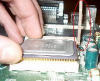
2. Insertion of the processor in the socket by respecting the locating pins (lack 1 or 2 pine - leg on one of the corners). It is impossible to insert a processor in the bad direction without folding a pin.
3. Press on the processor to install.
 4. By keeping the finger on the
processor, lower the barring lever of the processor (surrounded in red
on the photographs opposite).
4. By keeping the finger on the
processor, lower the barring lever of the processor (surrounded in red
on the photographs opposite).
For the 286, 386 and first 486 (before the DX2-66), the cooler is not necessary.
For processors 486, Pentium, Pentium III and K6-2 or K6-3 pass as in point 6. The processors according to require a perfect cooling. Here how to mount a ventilator on a processor.
 5. Use the thermal paste directly
stuck on the ventilator or scrape this paste on the ventilator (with a
flat screwdriver, it should not remain about it any more) and pose
thermal paste (silicone) on the processor. The
quantity to be put must just cover the unit with the pastille
processor in a uniform way, the pastille should not be visible more but
not need to put some more than 1 mm thickness. This solution is often
preferable.
5. Use the thermal paste directly
stuck on the ventilator or scrape this paste on the ventilator (with a
flat screwdriver, it should not remain about it any more) and pose
thermal paste (silicone) on the processor. The
quantity to be put must just cover the unit with the pastille
processor in a uniform way, the pastille should not be visible more but
not need to put some more than 1 mm thickness. This solution is often
preferable.
 6. Position the ventilator on the
processor while following the stages below.
6. Position the ventilator on the
processor while following the stages below.
A. Check the direction according to the 2 fixations on socket and cooler.
 B. The ventilator must be posed vertically of a block.
One should not pose the ventilator on a side and make lever to pose it
other (because of the thermal paste).
B. The ventilator must be posed vertically of a block.
One should not pose the ventilator on a side and make lever to pose it
other (because of the thermal paste).
 C. The cpu fan should not pose on the plastic of
the connector. For the old processors, this problem did not exist.
C. The cpu fan should not pose on the plastic of
the connector. For the old processors, this problem did not exist.
 D. Fix the fastener without "catch" on the
socket. Then, using a screwdriver (or better a key casing with the
groin) being used as lever, fix the second part. Be quiet, if the
fastener breaks, the use potential of the moterboard is ...
D. Fix the fastener without "catch" on the
socket. Then, using a screwdriver (or better a key casing with the
groin) being used as lever, fix the second part. Be quiet, if the
fastener breaks, the use potential of the moterboard is ...
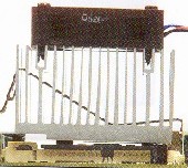
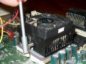
7. Insert the power
supply connector of the vent ilator in socket CPU FAN (new
motherboards). For the old ones, the ventilator was directly connected
on a connector of the power supply. The new ventilators are supplied on 3 wire.
The red (+) and the black (mass) are useful for the power supply. The yellow is
used as regulation. While cutting the yellow wire, the ventilator turns permanently.
ilator in socket CPU FAN (new
motherboards). For the old ones, the ventilator was directly connected
on a connector of the power supply. The new ventilators are supplied on 3 wire.
The red (+) and the black (mass) are useful for the power supply. The yellow is
used as regulation. While cutting the yellow wire, the ventilator turns permanently.
A first cause of breakdown if the PC does not start is an incorrect processor insertion in the socket, badly inserted. If the ventilator is not correctly in contact with the processor or if the ventilator under-is dimensioned, the microprocessor is likely to burn, irremediably destroyed. The current motherboards include a temperature sensor for the whole of the system and another for the processor. In the event of too important temperature, the PC is immediately cut. The maximum temperature is skeletal in the BIOS. Other motherboards do not start if the ventilator processor does not turn (in breakdown or connector CPUFAN not inserted).
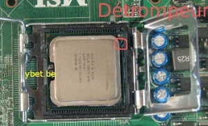
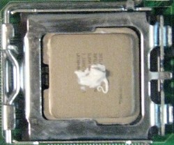
3. Pentium IV, Core and Core 2, I7, I5, ... Intel
 These processors use socket 775
and assimilate (1155,1156) but mothers map are not necessarily compatible with all models. In this case, the Pin are no longer on the integrated circuit (which just flat but good contacts in the socket. The processor must simply be placed in correct orientation before being
locked.
These processors use socket 775
and assimilate (1155,1156) but mothers map are not necessarily compatible with all models. In this case, the Pin are no longer on the integrated circuit (which just flat but good contacts in the socket. The processor must simply be placed in correct orientation before being
locked.
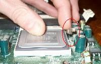
- Release lever to the left to raise the cache. Insert the processor respecting the direction (keyed on the ceramic part prevents reverse the direction). At least try not to put fingers on the metal part, it must be as clean as
possible.
 Keeping the lever open, tilt the metal on the processor cache, then close the lever against the socket to lock the metallic cache (in red in the picture). It must be perfectly secured on the
side.
Keeping the lever open, tilt the metal on the processor cache, then close the lever against the socket to lock the metallic cache (in red in the picture). It must be perfectly secured on the
side.- If it is not on the nine fan (replacement of the processor also requires to change this paste), delete the existing layer on both sides and put in just a little bit of thermal paste on the processor (for liquid Pastes into the brush, cover the entire surface with the thinnest possible
layer).
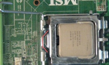
- For this Intel processor socket attaches with four legs that fit into the corresponding holes in the round of the socket (AMD models differently, attach to the plastic of the socket).
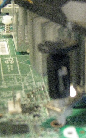 The meaning has no importance to the 4 white nipples which should first be inserted each in a respective fixing hole. Once done, press by turning the black areas at the top to lower the pine indoors. This will block the white parts and attach the fan to the
motherboard.
The meaning has no importance to the 4 white nipples which should first be inserted each in a respective fixing hole. Once done, press by turning the black areas at the top to lower the pine indoors. This will block the white parts and attach the fan to the
motherboard.- This method is effective if each white nipple is correctly blocked in its slot. Check if the installation is correct by returning the motherboard, the processor must be securely attached to its four fasteners.
A common cause of failure if the PC does not start is an insert incorrect processor in the socket, badly depressed or oxidation (to clean with a little denatured alcohol and let dry, then rub with a paper type paper towel to remove residues). If the fan is not properly in contact with the processor or the fan is undersized, the microprocessor may burn, irreparably damaged. Current boards include a probe temperature for the entire system and another for the processor. If the temperature is too high, the PC is immediately cut off. The maximum temperature is adjustable in the BIOS. Other motherboards do not start if the processor fan is running not (in failure or CPU FAN connector not inserted).
4. Memory insertion in the connector.
It is impossible to use a memory of a type in a connector different report (locating pin, dimension). By practice (and also because of certain problems on motherboards), one uses initially the slot 1, then the 2, then the 3
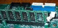
Fixings (here in white) must block the memory of each with dimensions perfectly.
The problem can come from the speed of the memories. If your memory is too fast, it will not be refreshed correctly (this problem is rather rare). On the other hand, if the memory is too slow for the motherboard (processor FSB), you lose speed and several difficulties can arise: not recognized memory, plantings...
A memory not recognized or recognized incorrectly (bad capacity) can come from various reasons:
- Defective, badly inserted memory
- Motherboard does not accept the memory sizes higher than a certain value. This problem comes from the too old motherboard, for example, chipsets INTEL 440 BX recognize Dimm 256 MB like 128 MB (but not of problems of operation).
In a modern motherboard, a parameter setting of the BIOS makes it possible to determine the speed of the memory automatically.
In the case of a motherboard including of the connectors report of various types, it is disadvised types mixing. According to the motherboard, you will be able for example to use Dimm 1 and Simm 1, but not Dimm 1 and 2 and Simm 1. All the cases of problem are possible.
Certain marks of memories are also incompatible with certain motherboards, even if this type of problem does not appear much any more with the new machines.
5. Fixing the motherboard and the peripheral boards.
The motherboard must be fixed on the bottom of the case separated by plastic spacers (cases AT) or metal (AT and ATX). Direct fixing on the case causes automatically short-circuit. (do not laugh, a customer did it to me). The number of spacer used must ensure the stability of the chart perfectly, that is to say 6 minimum.
The insertion of a peripheral chart (screen, network, its...) must be made cut off supply. In the case of a ATX power supply (for recall), the motherboard remains under tension if the PC is extinct. The electrical connector must be withdrawn before inserting or withdrawing an electronic chart. The charts must be perfectly inserted and fixed at the case. If it is not the case, the chart will not be detected, will cause plantings or even will short-circuit the motherboard.
In certain cases bottom-of-the-range, certain connectors are not usable because of incorrect size. A problem which one often encounters: the graphics accelerator is not correctly inserted in AGP connector.
For VLB board (486), with time, the motherboard subsides on the bottom and connector VLB is not correctly any more in contact. The only solution consists in slipping of the paperboard between the motherboard and the bottom of the case.
I already encountered some problem of compatibility between chipsets of graphics card and chipset of motherboards, mainly on the K-6 level of AMD. For the remainder, can pose problems of interruptions.
6. Fixing of the case connectors.
The switches, LED and speaker fit according to the motherboard (here ATX card). The direction of the connectors switch does not have importance, that of the LED, yes.
- HD LED must ignite when IDE port (hard disk, CD-Rom) functions. The respect of the direction (+ and -) is obligatory (if not reverse the connector). For 486 and the lower, the LED is connected on the chart controller and not on the motherboard. For controllers SCSI, a connector is also connected on the chart to accept this LED.
- the RESET button
- the ATX power supply switch (Power SW)
- LED power, connector with three pine with that of the medium not used. This LED with a direction, reverse-there if necessary. In certain cases (generally AT), this LED is connected directly on the power supply.
- Keyb Lock, often gathered with LED power, makes it possible to block the PC with a key opposite front. The keys are standard. In the event of problem, it is enough to remove the connectors. This key does not exist any more on the modern cases and modern computers.
- Turbo and turbo LED. These two connectors are specific to the first PC (until Pentium) and made it possible to return of speed processor to 8 MHz (8088). Useless, it posed problems, the Turbo connectors was to be put and tested. According to direction's of the connector, the PC functioned in 8 MHz and the turbo LED ignited (or not). Speed thus should be tested manually.
- Green LED (optional). This LED ignites (flickers) when the PC is in energy saving.
- Speaker. The direction does not have importance, considering the low power of high the speakers interns PC.
7. Hard disks IDE, CD-Rom reader and floppy drive connection
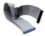 Respect the direction of connection. The 1 is
often noted on the motherboard by an inscription (figure 1 or one point).
Respect the direction of connection. The 1 is
often noted on the motherboard by an inscription (figure 1 or one point).
For the floppy drives, the 1 (often colored in red on the cable) is contrary to the connector of power supply of the reader. The reader must be connected on the connector after the cross cable (there is nevertheless the possibility of reversing it in the new BIOS). If the connector is reversed, the LED of the reader remains lit.
For the hard disks, there is also a mark on the connecting cable (often in red). The connector must be correctly inserted. The 1 (reference on the cable) is put in the connector hard disk of with dimensions of the power supply. The hard disks and readers CD-Rom (DVD/engraver) can be connected by 2 on each channel IDE (a primary channel and a secondary channel). On each channel, a peripheral must be as a Master and the other as a slave.
With the motherboards and ports UDMA 66/ 100/133, the cable uses 80 wire on the primary port, a cable 40 wire for the secondary peripherals. The position of the disc on the cable does not have importance in 40 wire and 80 wire. In 80 wire, the position is often noted for information on the cable. The primary port is often of blue color (white or black for the secondary). See also SATA connections
The starting hard disk must be in master like here. The readers CD/DVD/engraver fit on the secondary port of the motherboard. In many cases, the installation of the readers Cd on the primary port causes either nona recognition of the reader Cd or hard disk, or a deceleration of the hard disk which then works in UDMA 33 maximum (transfer of 33 MB/s instead of 100 - 133 MB/s). To insert an old hard disk as slave on the primary port combined with a new disc in UDMA 100/133 causes the same problems.
On the level of the positioning (master/ Slave) of CD/engraver/reader DVD. The former engravers must be positioned in master, if not, there are risks of losses of data. The reader of DVD must also be in master to avoid scintillations in the images. The position of the reader CD is indifferent. The new engravers include methods of correction of the type just Link and you can connect them as a slave (Slavic) if you use a reader DVD (him in master).
You also with some limits of capacities according to the size of the hard disk and the date of the BIOS. In this case, separate flasher the BIOS for the motherboards where it is possible (flashrom), the use of a hard disk of great capacity will be impossible.
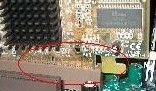
8. Motherboard installing for K6-2 and K6-3
These motherboards K6-2 and K6-3 of AMD always use the socket 321 contacts (identical to Pentium and Pentium MMX) call socket 7 but are definitely more advanced and with format ATX.
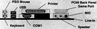
With format ATX, the connectors series and parallel, keyboard PS2 and mouse PS2 (sometimes the audio circuit) are established on the board. The ventilator processor feeds on the moterboard. The majority of these motherboards include temperature a sensor, even often 2: for the processor and for the whole of the case.
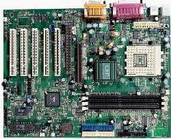
The board above (AOpen AX59 Pro) is not configured by bridgings, but by switch which one puts at 1 or to 0.
One finds of left on the right and upwards:
- buses: 2 ISA, 4 PCI and 1 AGP 2X
- the Floppy connector (with the back)
- the connector of power supply ATX
- external connections: LPT, COM, keyboard and mouse.
- the connectors reports: 2 Simm and 3 Dimm
- connectors of the case (see above).
- the socket processor
- 2 ports E-IDE
|
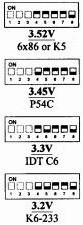
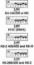
The supply voltage is regulated like above. Attention, the models 5V are not supported. You do not refer with the tensions above. The manufacturers of processor modify sometimes the voltage supply without preventing, even on two identical processors. Always use the tension written on the processor! |
|
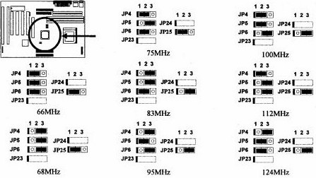
Select the external frequency of the processor, the Face Side Bus (FSB) above.
|
|
|
|
CPU Frequency = RATIO External Drunk Clock |
|
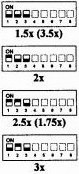
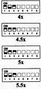
The following adjustment consists in regulating the multiplication factor according to the external frequency. This table shows the frequencies and multiplication for processors Pentium P54C, MMX P55C, K5, K6, K6-2 and K6-3, Cyrix). Certain models are not accepted because of the not recognized external frequencies (50 and 60 MHz) since the external frequency of this board starts to 66 MHz.
Some note:
- If your external frequency FSB is higher than 66 MHz, one needs memories 100 MHz.
- Be wary particularly of Cyrix on the level of the frequencies.
- K6-2 and K6-III are perfectly identical for insertion in a motherboard.
- If several possibilities exist, use the maximum external frequency (with the associated memories). If the PC plants: descend the external frequency and increase the factor ration.
9. Duron and Athlon socket A motherboard.
 A motherboard for socket A of AMD (Athlon
or Duron), the QDI KuDoz 7E/333 containing chipset VIA KT333
(North
Bridge) and VT8233A (South
bridge). She accepts the majority of Duron and Athlon (FSB of
100-200, 133-266 but not 166-333) in memory DDR (200/266/333),
included out of standard ports USB 1.1, series and parallel port, its
and port game (plays) in power supply ATX. Like any motherboard socket A (and
PGA 478 for Pentium IV), the processor is automatically detected (except
FSB in AMD). In addition to the port AGP 4X and 5 ports PCI, a CMR port is
included for a modem (on the right port AGP), but no more ISA ports.
A motherboard for socket A of AMD (Athlon
or Duron), the QDI KuDoz 7E/333 containing chipset VIA KT333
(North
Bridge) and VT8233A (South
bridge). She accepts the majority of Duron and Athlon (FSB of
100-200, 133-266 but not 166-333) in memory DDR (200/266/333),
included out of standard ports USB 1.1, series and parallel port, its
and port game (plays) in power supply ATX. Like any motherboard socket A (and
PGA 478 for Pentium IV), the processor is automatically detected (except
FSB in AMD). In addition to the port AGP 4X and 5 ports PCI, a CMR port is
included for a modem (on the right port AGP), but no more ISA ports.
The basic installation of the motherboard does not pose problems:
- standard connector ATX.
- connectors cases: power switch, Led hard disk, led power, announcer
- connector primary hard disk ATA 133 and secondary ATA 33.
- Floppy drive
- ventilator for processor (obligatory), 2 connector for optional ventilators of case.
- Bridging are definitely more complex. FSB: if bridging is put (closed), FSB of 100 MHz (Duron), if it is withdrawn: FSB of 133 (Athlon)
- Automatic control of the processor or overcloking. For recall, the speed of a processor is calculated by external speed (FSB) X multiplying (drunk ratio). For example, for Athlon XP 2000+ (turning in fact with 1.67 Ghz), the FSB is 133, the multiplier is thus of 12,5X. Athlon XP table shows the majority real speeds Athlon XP
Attention, the microprocessor FSB passes here from 133 MHz to 166 MHz. The board above does not accept them, it is necessary to use a KT400 of VIA like chipset (with normal place KT333)
In this case, you can also used the bridging of automatic control of V Core (supply voltage of the processor) or to manually put the tension (variable of 1,65V with 1,85V). Recall: overclocking can cause the destruction of the processor.
8. Jumper of protection BIOS the flashage of the BIOS is protected by defect in the SETUP but you can moreover put specific bridging on the motherboard.
9. Enable or disable the integrated sound board, is done here using 3 bridging.
10. In addition to 2 USB ports integrated into the back of the motherboard, you can connect 2 additional ports on the front face of the case.
In relation:
- Hardware course: Processors Evolution, lists and characteristic of the Processors used in the PC
- Course: The chipset Characteristics of the chipset used on the motherboards
- List chipsets: List chipsets (ports, memories, processors, FSB...)
- Course: Memory for PC: Memories used in the PC
|
The continuation of the hardware 1 tutorial > 23. Bios |
The hardware course 1 (computer and peripheral). The Hardware course 2 (network, server, ...)
![]()
Competences with the service of quality.